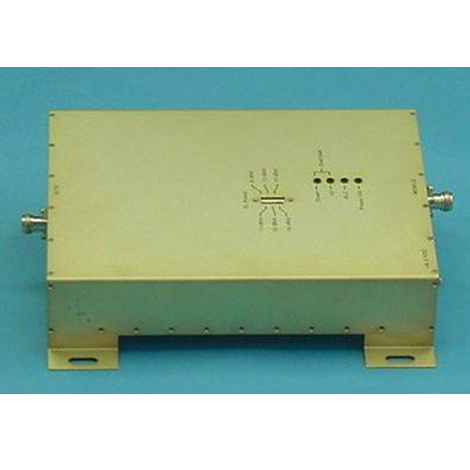
MR-UMTS70-20F
UMTS Bi-Directional Amplifier (WCDMA)
MR-UMTS70-20F is a full band UMTS linear repeater at low power consumption. It provides a cost effective answer for enhancing radio communication in buildings, basements, parking garages and other RF shielded environments.
Additional Features
Auto Setup.
Overload & Oscillation protection.
“Down Link” RF Power indication.
Specifications
Down Links
Down Link
Up Links
Up Link
Frequency Range
2110-2170 MHz
1920-1980 MHz
GAIN, typ.
70 dB
VSWR, max.
02:01
Input Impedance
50 Ohm
Output Power @ 1dB compression., dBm
30 dBm
Output IP3, dBm
40 dBm
Noise Figure, max.
5 dB
Pass Band Ripple
±3 dB
Biasing (Through Separate DC Connector)
6.7 VDC @ 2.5A, max
Range of ALC output power setting points, dBm.
20-6 dBm (up 8 set points)
Range of AGC, dB.
30 dB
Limited Output Power, dBm.
20 dBm
Protection from Oscillation and Overload
Automatic
1 dB points Bandwidth, typ.
15 MHz
Gain Characteristics of Antenna Element
-10 dBic minimum at 0° elevation
Filtering, typ.
40 dB @ ± 50 MHz
LNA Gain, typ.
25 dB
Noise Figure, typ.
1.6 dB
Output Impedance
50 Ohm
Power Supply through RF Cable, typ.
5±0.25 VDC ; 21 mA @ 5 VDC
Gain, min.
12 dBi
Polarization
Vertical & 2 Dual Slant ±45º
3 dB Beam-Width, H-Plane, typ.
120°
3 dB Beam-Width, E-Plane, typ.
70°
Input power, max.
20 Watt
Lightning Protection
DC Grounded
PIM, 3rd order, 2X20W
-150 dBc
VSWR typ.
02:01
Port to Port Isolation, typ.
-25 dB
Patterns
Directional
Axial Ratio
4 dB
Intercept Point
+10 dBm
Side Lobes, min.
-13 dB
Cross Polarization, min.
-20 dB
Front to Back Ratio, min.
-24 dB
3 dB Beam-Width, Horizontal, typ.
60°
3 dB Beam-Width, Vertical, typ.
55°
Front to Back Ratio, typ.
-30 dB
Individual Column - Gain, typ.
16 dBi
Individual Column - 3 dB Beam-Width, Azimuth Plane
90°±10°
Individual Column - Cross Polarization, typ.
-20 dB
Individual Column - Front to Back Ratio , min.
-30 dB
Array 4 Columns - Gain, typ.
21 dBi
Array 4 Columns - 3 dB Beam-Width, Azimuth Plane, typ.
25°
Array 4 Columns - Cross Polarization, typ
-20 dB
Array 4 Columns - Front to Back Ratio, min.
-30 dB
General - 3 dB Beam-Width, Elevation Plane, typ.
8°
General - Side Lobes, Elevation Plane, typ.
-12 dB
General - Input power, max
10W
General - Input Impedance
50 Ohm
General - Lightning Protection
DC Ground
3 dB Beam-Width, Azimuth, typ.
90°
3 dB Beam-Width, Elevation, typ.
19°
Side Lobes, Elevation Plane, typ.
-10 dB
Cross Polarization, typ.
-15 dB
Number of Beams (each polarization)
4
Beams Directions
±20°
Side Lobes, typ.
-12 dB
Polarization dual slant (opt)
Dual Slant ± 45°
Port to Port Isolation, min.
-24 dB
Isolation Between Bands
-30 dB
El. Downtilt Range
0° fixed
Gain, Vertical Pol.
16 dBi
GAIN, Dual Slant Pol.
16 dBi
GAIN, Horizontal Pol.
17 dBi
Cross Polarization, min. v-pol
-26 dB
-26 dB
-23 dB
-23 dB
-23 dB
Cross Polarization, min. h-pol
-23 dB
-25 dB
-23 dB
-20 dB
-15 dB
Cross Polarization, max
ETSI EN 302 085 v1.2.3 TS2 Range 1
Front to Back Ratio, max.
ETSI EN 302 085 v1.2.3 TS2 Range 1
PIM, typ.
-140 dBc
Azimuth scan step
(3-7)°
Azimuth beam control range *
+/-45° *
Modes (External control)
Rx or Tx, Beamforming or Broadcast
Beamforming (V&H) Gain of passive antenna part, typ.
21dBi
Beamforming (V&H) RX Mode: Gain with LNA's (Broadside), typ.
32dBi
Beamforming (V&H) RX Mode: Noise figure (Rx channel), typ.
5-6 dB
Beamforming (V&H) TX Mode: Output Operating RF Power (Output PA), typ
19-23dBm
Beamforming (V&H) TX Mode: Gain with PA (Broadside), typ.
40dBi
Broadcast (V&H) Gain of passive antenna part, typ.
15dBi
Broadcast (V&H) Azimuth 3dB Beam width
60°-70°
Broadcast (V&H) Azimuth 5dB Beam width
90°-100°
Broadcast (V&H) RX Mode: Gain with LNA's, typ.
33dBi
Broadcast (V&H) TX Mode: Output Operating RF Power (Output PA), typ.
19-23dBm
Broadcast (V&H) TX Mode: Gain with PA, typ.
34dBi
Max Input RF Power (damage)
18dBm
Beam and Modes selection time, typ.
1-2 us
External Power supply
+5V ; PoE (+48 ?)
External control interface
GPIO (7 wires)
Down tilt, E-Plane
2°
Side Lobes, min. H-pol
ETSI EN 302 085 V1.2.3 CS3
Side Lobes, min. V-pol
ETSI EN 302 085 V1.2.3 CS2
Input power, min.
100 Watt
Port to Port Isolation, min. Intra-Band
-17 dB
-30 dB
PIM 3rd order (2 x 43 dBm carrier), min.
-150 dBc
Cross-polar Discrimination at 0°, min.
-20 dB
Cross Polarization Discrimination, typ.
-20 dB
Array Element Spacing
136 mm (1.5? on 3.3 GHz)
Angle between 2 beams
180°
* - For Azimuth beam control range +/- (30-45)° : Gain = Gain, typ. (~3) dB; Side Lobes < -(1-3)dB.